|
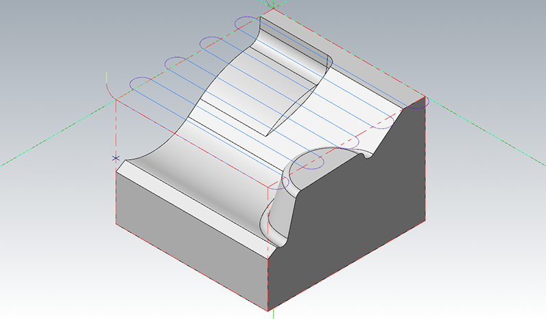
The Face strategy is designed for removing stock above a given horizontal plane.
In the large area, the tool is selected, or a new tool can be created from the right click menu. The fields below are automatically updated from the tool selected above. The tool drawing to the right is updated each time a field is exited, to reflect the changed value. The right click menu is also used to access the HSM tool library, described below.
The flute length doesn't have an effect on the shape of the cutter paths unless a taper angle is applied. Tapered tools add the shape of a cone of the given taper angle from the vertical axis. The bottom of the (truncated) cone is tangential to the shape at the tip, and the top is at the flute length above the tip. For tapered tools, the tool definition is straightforward for ball nosed and flat bottomed tips, but for bull nosed tips the standard convention is more complicated: the shaft diameter refers to the diameter of the bottom of the conical surface and not the diameter of the virtual toroidal shape that would be within the tapered shape.

|

|
In the section Shaft and holder you can define holder and shaft collision checks and how the toolpath should respond to detected collisions. In particular, this is where you can define to tilt the tool in case of a collision, effectively creating a 5-Axis toolpath.
Note that these collision checks require additional calculation time when the toolpath is generated, but ensures that the shaft and holder do not collide with the part if used.
The following parameters can be set to control the collision detection (note that not all parameters are available for all strategies):
Collision detection policy
The dropdown menu lets you select how HSM Performance Pack should react to a detected holder collision. The following options are available (depending on the selected strategy):
Ignore
With the option Ignore, collisions between the shoulder, shank, holder and the work piece are ignored.

|
Clearance height
The Clearance height defines the first height to which the tool moves before the start of the toolpath. The height is relative to the top of the surface to be machined.
The field Absolute clearance height can be enabled to define an absolute Z value instead.
Retract height
The Retract height defines the height to which the tool retracts between cutting passes. The linking moves at this height are carried out at rapid speed. The height is relative to the top of the surface to be machined.
The field Absolute retract height can be enabled to define an absolute Z value instead.
Safe distance
The Safe distance defines the minimum distance between the tool and the part surfaces during shortest path retract moves. This distance is measured after the stock to leave has been applied, so if a negative stock to leave is used, special care should be taken that the safe distance is large enough to ensure that no collisions occur.
Retraction policy
The Retraction policy determines how moves between cutting passes are done. Shortest path is the shortest possible path (which often includes moves in all three axes), Minimum retraction is straight up to the lowest height where the tool will be clear of the part (by safe Z distance), and Full retraction is to the clearance plane.
Allow rapid retract
By enabling Allow rapid retract, vertical retract moves will be carried out at rapid speed. If this is not enabled, retracts will be carried out at the lead-out feedrate.
Lead radius
Lead radius defines the radius of the arc component of the lead-in/out movement. The radius can be specified as a percentage of the tool diameter or as an absolute value.
Lead out radius
Lead out radius defines the radius of the horizontal arc component of the lead out movement. The radius can be specified as a percentage of the tool diameter or as an absolute value. You need to enable Explicit lead out in order to specify a separate horizontal lead out radius. Otherwise, the same radius will be used for lead-in and lead-out.
Linear lead distance
Linear lead distance lead distance defines the length of the linear segment component of the lead-in/out movement.
Linear lead out distance
Lead out radius distance defines the length of the linear segment component of the lead-in/out movement. You need to enable Explicit lead out in order to specify a separate linear lead out distance. Otherwise, the same distance will be used for lead-in and lead-out.
Keep down distance
The Keep down distance defines a length below which retracts are avoided. This means that lead-in and lead-out moves are still generated below this length, but the tool is only lifted up slightly.
Max transition distance
Use the parameter Max transition distance to define a maximum allowed length for transitions between cutting passes. If the distance between two passes is greater than the Max transition distance, the tool retracts or is lifted up and a lead-out and lead-in are generated.
Contact ramp policy
From the dropdown menu contact ramp policy you can select the method by which ramps should be carried out between different cutting depths. The available options are:
Straight line: This defines that the transitions are simple straight lines between two cutting passes.
Curve: In this mode, the transitions are smooth curves which are tangential to the cutting passes at both ends of the transition.
Disabled: This disables transition moves.

|
Tolerance
Tolerance defines the maximum value the toolpath is allowed to deviate from the surface of the input geometry. A small tolerance value yields more precise toolpaths at the expense of longer computation times.
Machining angle
With the machining angle the generated toolpath can be rotated in the XY-plane. Usually this is desirable to ensure that the tool does not raster along one of the principle axes of the machine.
Maximum stepdown
The stepdown is the maximum vertical distance between two cutting levels. Note that the actual stepdown may be less than the value specified in stepdown. This is because HSM Performance Pack will automatically reduce the stepdown to ensure that cuts are carried out at the minimum depth and maximum depth, and that all Z-level cuts are spaced evenly.
Axial stock to leave
Axial stock to leave defines the stock to leave in the Z-direction, i.e. in the direction along the tool axis. Axial stock to leave lifts the tool up from the surface by the specified distance.
Cutting mode
Available options are the following:
One way
Zig zag
One path
Constant cut
Maximum stepover
The stepover is the distance between two cutting passes. The stepover must always be less than or equal to the tool diameter since otherwise the toolpath might leave stand-ups between cutting passes.
Trim Passes
When you activate trim passes, aircuts are trimmed away, and the tool retracts to move towards the beginning of the next cut. When the option is deactivated, that tool will remain at cutting height when it passes over holes or gaps in the selected geometry.
Even steps
HSM Performance Pack will automatically reduce the stepdown to ensure that all Z-level cuts are spaced evenly.
Stepdown
The stepdown is the maximum vertical distance between two finishing cutting levels.
Number of levels
Specifies number of finishing cuts.
Across
Specifies distance for extending machining area in across cutting direction.
Along
Specifies distance for extending machining area in along cutting direction.
Direction
With the dropdown menu direction you can specify in which direction the tool will move along the surface. You can select climb milling or conventional milling.
Confine depth
Activate confine depth to specify depth limits for the toolpath.
Minimum depth
The minimum depth is the height at which the cuts begin.
Maximum depth
The maximum depth is the final cutting depth of the operation.

|
Add...
Click the Add... button to select the specific surfaces that should be machined by this operation.
Add all
Click the Add all button to select all surfaces to be machined by this operation.
Remove all
Click the Remove all button to remove all surfaces from the selection and so they are not machined by this operation.
Boundaries and points
The list Boundaries and points shows the boundaries and points for the operation. Boundaries and points can be added or removed by using the buttons Add boundaries... or Remove all.
Add boundaries
The Add boundaries... button allows the user to add one or more points or boundaries to the operation.
Remove all
The Remove all button removes all boundaries and points from the operation.
Remove
The Remove button only removes the selected boundary or point from the operation.
Manager...
The Manager... button enables you to switch to the Mastercam chain manager, and allows the boundaries or points to be edited there.
Select by entities...
The Select by entities... button changes to the graphics window, where the user can select an entity. The boundary containing that entity (if any) is then selected.
Type
From the dropdown menu type the type of boundary can be selected. The available options are:
Machining
The toolpath tab contains various parameters which are needed to configure the toolpath and properly execute it on the CNC machine, such as arc filtering and other toolpath filters.

|
Arc filtering
The checkboxes under Arc filtering let you configure in which planes (XY-plane, XZ-plane, YZ-plane or helical arcs) arcs should be output to the machine as actual arcs (i.e. G2/G3), instead of being output as line segments (G1).
Minimum radius
The Minimum radius defines the radius below which an arc is output as line segments.
Maximum radius
The Maximum radius defines the radius above which an arc is output as line segments.
Minimum chord length
The Minimum chord length defines the arc chord length below which an arc is output as line segments.
Linearization tolerance
The Linearization tolerance is the tolerance used when arcs are to be converted to line segments, either because arcs are disallowed in that plane, or because the arc is too large or too small.
Arc fitting
Use the option Arc fitting to fit arcs where it is possible.
Maximum error
Defines the maximum error (distance) of the arc fitting to the geometry.
Filtering policy
Rapid filtering defines when rapid moves should be converted to linear moves (G1 in ISO code) at a high feed rate. The following filtering policies are available:
Preserve rapid movement: Rapid moves are always output as rapid moves (G0 in ISO code), even if they are in all three axes simultaneously. This option should only be selected if rapid moves on the machine are synchronized as linear moves.
Preserve Z-axis and XY-plane rapid movement: Rapid moves are output as rapid moves (G0 in ISO code) if they are along the Z axis or in the XY plane, but are converted to linear moves (G1 in ISO code) at a high feed rate if they are in all three axes.
Preserve vertical rapid movement: Rapid moves are output as rapid moves (G0 in ISO code) if they are vertical (i.e. along the Z axis), and are otherwise converted to linear moves (G1 in ISO code) at a high feed rate.
Preserve horizontal rapid movement: Rapid moves are output as rapid moves (G0 in ISO code) if they are horizontal (i.e. in the XY plane), and are otherwise converted to linear moves (G1 in ISO code) at a high feed rate.
Preserve one axis rapid movement: Rapid moves are output as rapid moves (G0 in ISO code) if they are in one axis only, and are otherwise converted to linear moves (G1 in ISO code) at a high feed rate.
Map to high feed cutting: All rapid moves are converted to linear
moves (G1 in ISO code) at a high feed rate.
High feed rate
High feed rate defines the feed rate used when rapid moves (G0 in ISO code) are converted to linear moves (G1 in ISO code).
Depth compensation
Depth compensation lets you choose in which way the toolpath should be vertically adjusted to the tool radius. The following options are available:
Tool center
The output toolpath corresponds to the path of the tool center.
Tool tip
The output toolpath corresponds to the path of the tool tip.
Miscellaneous
The Settings button opens up the Mastercam dialog for setting the miscellaneous values.
The operation tab lets you define important parameters for the execution of the toolpath on the machine. For example, here you can set the file name of the output NC file, define the working coordinate system, or configure the line numbering of the output file.

|
Title
In the Title field you can define the name of the operation as it will be displayed in the Operation manager of Mastercam.
Comment
The Comment field lets you add an additional description of your machining strategy, and can be used to further document parameters, purpose etc. of the operation.
Program number
The field Program number lets you give the output NC program a number.
Sequence start
Sequence start defines the starting line number of the output NC program.
Sequence increment
The Sequence increment defines the increments in the line numbering of the output NC program.
NCI path
In the field NCI path you can define the name and path under which the output file should be saved. Click the icon [...] in the field to browse your file system for a desired directory.
Tool view
The parameters under Tool view define the tool plane and origin for 5 axis positioning.
You can define the X, Y and Z coordinate of the tool view through the respective fields. Furthermore, you can select the origin and select the tool plane by clicking on the respective buttons.
Working coordinate system
The parameters under Working coordinate system defines the working coordinate system used in the operation.
You can define the X, Y and Z coordinate of the working coordinate system through the respective fields. Furthermore, you can select the origin by clicking on the respective button.